
This website uses cookies. For further information on how we use cookies you can read our Privacy and Cookie notice
HomeAutomobileCar Electronics & AccessoriesCar Electronics AccessoriesAudio & Video AccessoriesPortable Device Car Mounts6 Digits DIY Clock Kit Auto Display Time DIY Alarm Clock Soldering Practice Kit for Students Diyers DIY Enthusiasts
/product/74/0278652/1.jpg?7915)
Share this product
Shipped from abroad
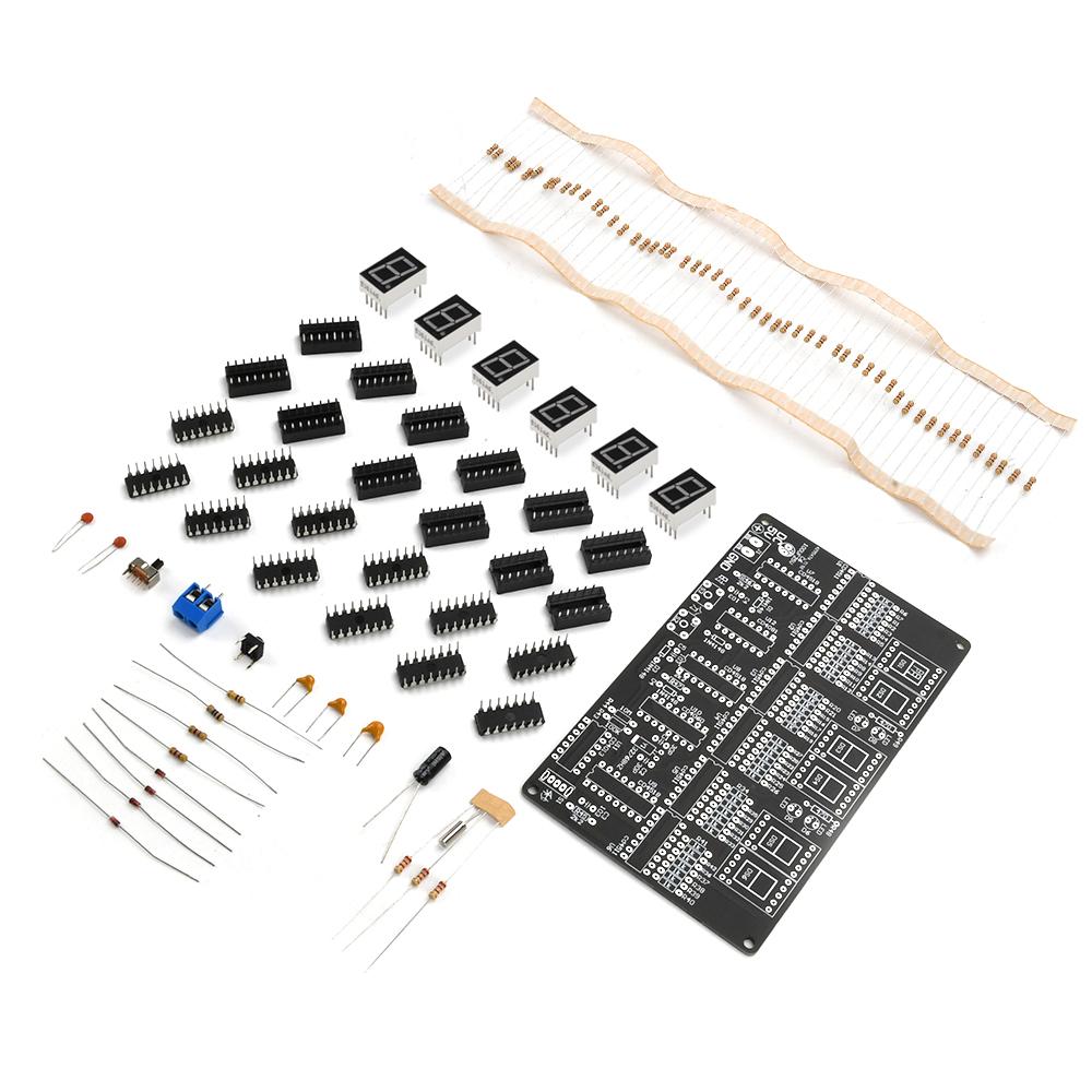
6 Digits DIY Clock Kit Auto Display Time DIY Alarm Clock Soldering Practice Kit for Students Diyers DIY Enthusiasts
GH₵ 1,037.00
GH₵ 1,526.6032%
In stock
Order above GHC 150 on Jumia Express items & get free delivery | regular delivery from GH₵ 82.11 to Tema
0 out of 5
(No ratings available)Variation available
Promotions
Delivery & Returns
Shipped from abroad
Choose your location
Pickup Station
Delivery Fees GH₵ 82.11
Ready for pickup between 24 October & 29 October when you order within next 23hrs 18mins
Door Delivery
Delivery Fees GH₵ 94.01
Ready for delivery between 24 October & 29 October when you order within next 23hrs 18mins
Return Policy
Free return within 15 days for all eligible items.Details
Seller Information
Fueran
60%Seller Score
Be the first to follow
Seller Performance
This seller does not have enough history for us to evaluate his performance yet
Product details
DIY Supplies : ELECTRICAL
Origin : Mainland China
Certification : none
Parameters:
1. This is a 24-hour digital circuit clock kit that uses chips such as CD4518, CD4511, CD4081, CD4013, and CD4060
2. The product is made of high-quality materials with guaranteed quality
3. Can be used for teaching, training, and welding, very suitable for DIY enthusiasts
4. Stable product performance and long service life
5. Using a red display digital tube, the numbers are clear and clear at a glance
Product Introduction:
This product is a 24-hour digital circuit clock, using chips such as CD4518, CD4511, CD4081, CD4013, CD4060, etc. The circuit does not contain a microcontroller, so there is no program, and the hours, minutes, and seconds can be calibrated without an alarm function.
This kit mainly consists of a second signal generator, a counter, decoding display, and a timing circuit. The second pulse is accurately divided by a high-frequency signal generator to obtain a 1HZ square wave signal, which is more accurate in timing.
The second signal generator consists of CD4060 and CD4013, generating a square wave signal with a frequency of 1HZ. CD4060 is a 14 stage binary frequency divider/oscillator. It forms a 32768HZ oscillator with external resistors R44, R43, C1, C2, and Y1. After 14 levels of binary frequency division, a square wave signal with a frequency of 2HZ is obtained at pin 3. CD4013 contains two independent D flip-flops, one of which is configured as a binary counter through wiring. The second signal can be obtained by binary counting the input 2HZ square wave signal. CD4518 is a double decimal addition counter. Use three CD4518 clocks to time the hour, minute, and second, with the hour configured as 24 base and the minute and second configured as 60 base. The counting result of CD4518 is output in BCD code form from pins Q0-Q3 to the BCD decoder CD4511. CD4511 converts the BCD code into a display segment code that illuminates the corresponding digital tube, forming recognizable Arabic numerals on the digital tube, and visually displaying the current timing result.
The minute and second bits are 60 base counts, and the second signal is introduced to the EN end of CD4518 through switch S1, Add 1 to the falling edge of the signal every second If the second signal is connected to the CLK end of CD4518, 1 is added to the rising edge of each second signal. When the counter counts to 9, Q0-Q3 outputs 1001, which means Q3 is 1. As it is a decimal counter, when the next second signal arrives, the counter changes from 9 to 0, and Q0-Q3 outputs 0000, forming a falling edge signal on Q3. This signal is introduced to the ten bit counter of the second counter. After every 10 full counts, the ten bit counter adds 1 When the ten digit count value reaches 6, Q0-Q3 outputs 0110, meaning that Q1 and Q2 are both 1. Q1 and Q2 output 1 through an AND gate and connect it to the reset end of the counter, causing the counter to advance from 6 to 0, completing a cycle of 60 decimal counting. The reset signal is also used as the counting signal of the minute counter, adding 1 to the minute counter every 60 seconds. The minute counter is also in 60 base. When the minute counter reaches 60, the ten bits of the minute counter also receive a reset signal from one AND gate, causing the time counter value to increase by 1. When the counter reaches 24, the ten bits of Q0-Q3 are 0010 and the one bit of Q0-Q3 is 0100. By performing an algorithm to sum the ten bits of Q1 and the one bit of Q2, it is connected to the reset terminals of the two counters, Set the hour bit count to zero after reaching 24, achieving a 24 base count.
DIY bulk Package:
PCB board X1
0.56 digital tube 1 bit common cathode X6
470 Ohm resistor X2
1K resistor X50
2.2K resistor X3
100K resistor X1
10M resistor X1
1N4148 diode X4
103 single stone capacitor X3
32.768KHZ crystal oscillator X1
30P porcelain chip capacitor X2
25V 100UF capacitor X1
KF301-2PX1
6 * 6 * 5 button X1
12D07 toggle switch X1
16P IC holder X10
14P IC holder X 2
CD4511X6
CD4518X3
CD4081X1
CD4060X1
CD4013X1
Package include:
Loose parts X1


Specifications
Key Features
DIY Supplies : ELECTRICAL
Origin : Mainland China
Certification : none
Parameters:
1. This is a 24-hour digital circuit clock kit that uses chips such as CD4518, CD4511, CD4081, CD4013, and CD4060
2. The product is made of high-quality materials with guaranteed quality
3. Can be used for teaching, training, and welding, very suitable for DIY enthusiasts
4. Stable product performance and long service life
5. Using a red display digital tube, the numbers are clear and clear at a glance
Product Introduction:
This product is a 24-hour digital circuit clock, using chips such as CD4518, CD4511, CD4081, CD4013, CD4060, etc. The circuit does not contain a microcontroller, so there is no program, and the hours, minutes, and seconds can be calibrated without an alarm function.
This kit mainly consists of a second signal generator, a counter, decoding display, and a timing circuit. The second pulse is accurately divided by a high-frequency signal generator to obtain a 1HZ square wave signal, which is more accurate in timing.
The second signal generator consists of CD4060 and CD4013, generating a square wave signal with a frequency of 1HZ. CD4060 is a 14 stage binary frequency divider/oscillator. It forms a 32768HZ oscillator with external resistors R44, R43, C1, C2, and Y1. After 14 levels of binary frequency division, a square wave signal with a frequency of 2HZ is obtained at pin 3. CD4013 contains two independent D flip-flops, one of which is configured as a binary counter through wiring. The second signal can be obtained by binary counting the input 2HZ square wave signal. CD4518 is a double decimal addition counter. Use three CD4518 clocks to time the hour, minute, and second, with the hour configured as 24 base and the minute and second configured as 60 base. The counting result of CD4518 is output in BCD code form from pins Q0-Q3 to the BCD decoder CD4511. CD4511 converts the BCD code into a display segment code that illuminates the corresponding digital tube, forming recognizable Arabic numerals on the digital tube, and visually displaying the current timing result.
The minute and second bits are 60 base counts, and the second signal is introduced to the EN end of CD4518 through switch S1, Add 1 to the falling edge of the signal every second If the second signal is connected to the CLK end of CD4518, 1 is added to the rising edge of each second signal. When the counter counts to 9, Q0-Q3 outputs 1001, which means Q3 is 1. As it is a decimal counter, when the next second signal arrives, the counter changes from 9 to 0, and Q0-Q3 outputs 0000, forming a falling edge signal on Q3. This signal is introduced to the ten bit counter of the second counter. After every 10 full counts, the ten bit counter adds 1 When the ten digit count value reaches 6, Q0-Q3 outputs 0110, meaning that Q1 and Q2 are both 1. Q1 and Q2 output 1 through an AND gate and connect it to the reset end of the counter, causing the counter to advance from 6 to 0, completing a cycle of 60 decimal counting. The reset signal is also used as the counting signal of the minute counter, adding 1 to the minute counter every 60 seconds. The minute counter is also in 60 base. When the minute counter reaches 60, the ten bits of the minute counter also receive a reset signal from one AND gate, causing the time counter value to increase by 1. When the counter reaches 24, the ten bits of Q0-Q3 are 0010 and the one bit of Q0-Q3 is 0100. By performing an algorithm to sum the ten bits of Q1 and the one bit of Q2, it is connected to the reset terminals of the two counters, Set the hour bit count to zero after reaching 24, achieving a 24 base count.
DIY bulk Package:
PCB board X1
0.56 digital tube 1 bit common cathode X6
470 Ohm resistor X2
1K resistor X50
2.2K resistor X3
100K resistor X1
10M resistor X1
1N4148 diode X4
103 single stone capacitor X3
32.768KHZ crystal oscillator X1
30P porcelain chip capacitor X2
25V 100UF capacitor X1
KF301-2PX1
6 * 6 * 5 button X1
12D07 toggle switch X1
16P IC holder X10
14P IC holder X 2
CD4511X6
CD4518X3
CD4081X1
CD4060X1
CD4013X1
Package include:
Loose parts X1
Origin : Mainland China
Certification : none
Parameters:
1. This is a 24-hour digital circuit clock kit that uses chips such as CD4518, CD4511, CD4081, CD4013, and CD4060
2. The product is made of high-quality materials with guaranteed quality
3. Can be used for teaching, training, and welding, very suitable for DIY enthusiasts
4. Stable product performance and long service life
5. Using a red display digital tube, the numbers are clear and clear at a glance
Product Introduction:
This product is a 24-hour digital circuit clock, using chips such as CD4518, CD4511, CD4081, CD4013, CD4060, etc. The circuit does not contain a microcontroller, so there is no program, and the hours, minutes, and seconds can be calibrated without an alarm function.
This kit mainly consists of a second signal generator, a counter, decoding display, and a timing circuit. The second pulse is accurately divided by a high-frequency signal generator to obtain a 1HZ square wave signal, which is more accurate in timing.
The second signal generator consists of CD4060 and CD4013, generating a square wave signal with a frequency of 1HZ. CD4060 is a 14 stage binary frequency divider/oscillator. It forms a 32768HZ oscillator with external resistors R44, R43, C1, C2, and Y1. After 14 levels of binary frequency division, a square wave signal with a frequency of 2HZ is obtained at pin 3. CD4013 contains two independent D flip-flops, one of which is configured as a binary counter through wiring. The second signal can be obtained by binary counting the input 2HZ square wave signal. CD4518 is a double decimal addition counter. Use three CD4518 clocks to time the hour, minute, and second, with the hour configured as 24 base and the minute and second configured as 60 base. The counting result of CD4518 is output in BCD code form from pins Q0-Q3 to the BCD decoder CD4511. CD4511 converts the BCD code into a display segment code that illuminates the corresponding digital tube, forming recognizable Arabic numerals on the digital tube, and visually displaying the current timing result.
The minute and second bits are 60 base counts, and the second signal is introduced to the EN end of CD4518 through switch S1, Add 1 to the falling edge of the signal every second If the second signal is connected to the CLK end of CD4518, 1 is added to the rising edge of each second signal. When the counter counts to 9, Q0-Q3 outputs 1001, which means Q3 is 1. As it is a decimal counter, when the next second signal arrives, the counter changes from 9 to 0, and Q0-Q3 outputs 0000, forming a falling edge signal on Q3. This signal is introduced to the ten bit counter of the second counter. After every 10 full counts, the ten bit counter adds 1 When the ten digit count value reaches 6, Q0-Q3 outputs 0110, meaning that Q1 and Q2 are both 1. Q1 and Q2 output 1 through an AND gate and connect it to the reset end of the counter, causing the counter to advance from 6 to 0, completing a cycle of 60 decimal counting. The reset signal is also used as the counting signal of the minute counter, adding 1 to the minute counter every 60 seconds. The minute counter is also in 60 base. When the minute counter reaches 60, the ten bits of the minute counter also receive a reset signal from one AND gate, causing the time counter value to increase by 1. When the counter reaches 24, the ten bits of Q0-Q3 are 0010 and the one bit of Q0-Q3 is 0100. By performing an algorithm to sum the ten bits of Q1 and the one bit of Q2, it is connected to the reset terminals of the two counters, Set the hour bit count to zero after reaching 24, achieving a 24 base count.
DIY bulk Package:
PCB board X1
0.56 digital tube 1 bit common cathode X6
470 Ohm resistor X2
1K resistor X50
2.2K resistor X3
100K resistor X1
10M resistor X1
1N4148 diode X4
103 single stone capacitor X3
32.768KHZ crystal oscillator X1
30P porcelain chip capacitor X2
25V 100UF capacitor X1
KF301-2PX1
6 * 6 * 5 button X1
12D07 toggle switch X1
16P IC holder X10
14P IC holder X 2
CD4511X6
CD4518X3
CD4081X1
CD4060X1
CD4013X1
Package include:
Loose parts X1
What’s in the box
1*package
Specifications
- SKU: GE779CA4J5D95NAFAMZ
- Model: avoid chenicals
- Production Country: China
- Size (L x W x H cm): 12 x 13 x 14 cm
- Weight (kg): 1
- Color: Matches the image
Verified Customer Feedback

This product has no ratings yet.
/product/74/0278652/1.jpg?7915)
6 Digits DIY Clock Kit Auto Display Time DIY Alarm Clock Soldering Practice Kit for Students Diyers DIY Enthusiasts
GH₵ 1,037.00
GH₵ 1,526.6032%
Questions about this product?
